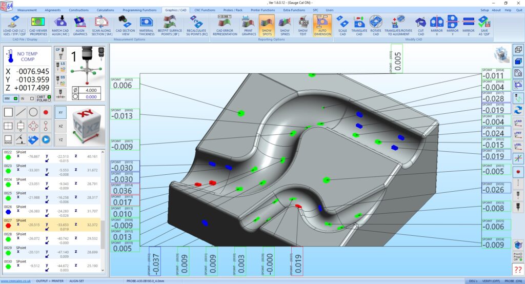
CAD data can be displayed and worked with any colour scheme format.
The unique colour mixing windows allows the background ,wire frame, shaded view and results to be fully customised.
The component can be aligned by simple geometric measuring functions , using selected features from CAD model and probing as directed or by free fitting of selected points on the CAD model and running Best fit functions.
Measured results can be output in various formats including numeric and graphical. The use of colour coded hexagonal spot points on the shaded model makes a graphic very quick and easy to assimilate.
Hexagons, spikes or text results can be simply selected by checking different option boxes. Surface and geometric results can be displayed on the same graphic report.
3D-Pro64(+CAD) FUNCTIONS
Cad Gauge Points can be loaded and used for programming. Layer selection,Best Fit Surface Points & Match Cad Alignment, RPS set up .View In Outline , Wire Frame & Shaded Views. Mirror , Rotate , Scale , Translate & Section Cad. Add Material Thickness & Offset Change Cad & Probe Viewer Properties. Show Results With Text, Spikes , Spots & Labels.
Interrogate Cad File, Cad Surface Selection Edge & Surface Points Write and Run Programs